Determination of the Young’s modulus of a metal (steel) in the form of a wire
Required Apparatus
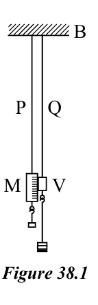
Two uniform steel wires of lengths about 3 m and diameter about 0.5 mm each, both hung from the, same rigid support, the main scale (M) calibrated in mm and alongside a vernier scale (V) attached, to the other wire, a pan to bear weights, a metre ruler, a micrometer screwgauge and a set of 1⁄2 kg, weights.
Scientific Theory
If is the load suspended, the cross-sectional area of the wire, the extension of the wire, and the original length of the wire,
Young's modulus is defined as:
Therefore,
Rearranging,
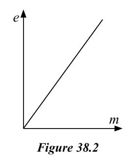
For the graph of against ,
Experimental Method
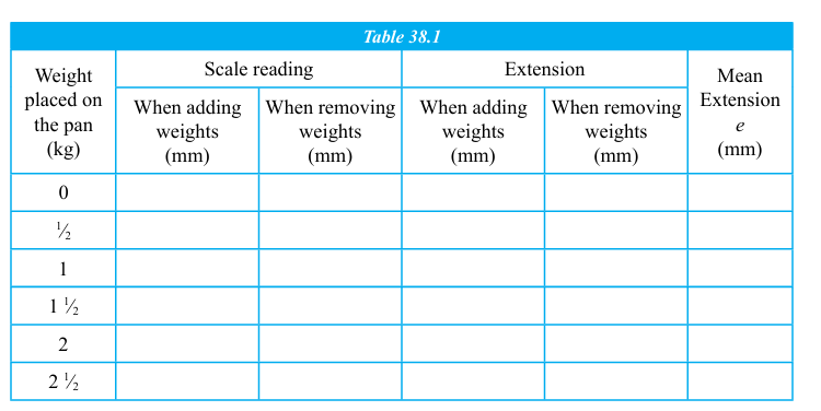
As shown in Figure 38.1, hang a dead load from wire P to which the main scale is attached, to keep it free of bends. Hang the pan from the wire Q to which the vernier scale is attached. Observe the scale reading using the vernier and record it. Now place an initial 1⁄2 kg on the pan and obtain the reading on the scale again. Continue adding 1⁄2 kg to the load each time and obtain the corresponding scale reading for each total load. After obtaining fi ve/ six readings in this manner remove the added weights in the same order by 1⁄2 kg each time and obtain scale readings until the load returns to the initial value. Enter all readings in the Table 38.1. Measure the length of wire Q from the support up to the vernier using metre ruler and record it. Also measure using the micrometer screw gauge the diameter of the cross section of the wire Q at three different places, taking two readings normal to each other at every place and record the readings
Diameter of the wire:
- (i) .......... mm
- (ii) .......... mm
- (iii) .......... mm
- (iv) .......... mm
- (v) .......... mm
- (vi) .......... mm
Mean diameter of the wire:
Area of cross-section of the wire:
Length of wire (from support to the vernier):
On the same axes, plot separate graphs of against for the loading and unloading data. Determine the gradients of both graphs. Use the mean of the two gradients to calculate the Young's modulus of the material of the wire.
Gradient of the graph of against :
Taking
Young's modulus is calculated using:
Important Points
- Since both wires are cut from the same material and suspended from the same rigid support, any errors due to extension of the support or temperature changes affect both wires equally and are largely canceled out.
- By removing the loads and taking unloading readings, it is possible to verify whether the elastic limit of the wire has been exceeded. If the wire does not return to its original length, permanent deformation has occurred.
- During loading, bends and kinks in the wire may straighten and appear as additional extension. These effects are revealed during unloading, so taking both loading and unloading readings helps correct such errors.
- The wire should be free from bends, twists, and kinks before starting the experiment.
- The load should be added and removed gradually to avoid sudden jerks that may permanently deform the wire.
- Readings should be taken only after the wire has come to rest.
- The pointer and scale should be viewed at eye level to avoid parallax error.
- The wire should not be loaded beyond its elastic limit.
- The experiment should be carried out in a location with minimal temperature fluctuations, since the length of the wire changes with temperature.
- Multiple diameter measurements should be taken at different points along the wire using a micrometer screw gauge, and the mean value should be used to reduce error.