Construction of the transfer characteristic curve between IB and IC of a transistor in common emitter configuration
Required Apparatus
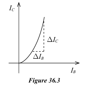
- 2SD400 silicon transistor, - Two 5 kΩ potential dividers (potentiometers, B type), - 10 kΩ resistor, - 100 Ω resistor, - Two digital multimeters, - One used as an ammeter to measure current in the range 10 V, 100 μA, - One used as a voltmeter in the range 10 V, 5 μA, - Analogue multimeter, - 25 mA range, - 12 V d.c. power supply (or a 6 V accumulator), - Circuit board (project board / breadboard), - Connecting wires
Scientific Theory
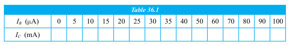
When is plotted against , a curve similar to the one shown in Figure 36.3 is obtained.
The gradient of the linear portion of the graph gives the direct current gain of the transistor.
Experimental Method
-
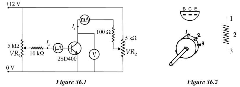
Set up the circuit on the circuit board as shown in Figure 36.1.
-
Rotate both potential dividers and anticlockwise completely (middle terminal will reach close to the Earth terminal).
-
Connect the power supply to the circuit.
-
Rotate slowly and clockwise until the voltmeter reading () becomes 5 V.
-
Since this reading changes when is changed, should be kept constant by adjusting .
-
Rotate slowly clockwise and measure the values of starting from 0 to 10 μA each time.
-
Record all values of relevant to the values of in Table 36.1.
| (μA) | 0 | 5 | 10 | 15 | 20 | 25 | 30 | 35 | 40 | 50 | 60 | 70 | 80 | 90 | 100 |
|---|---|---|---|---|---|---|---|---|---|---|---|---|---|---|---|
| (mA) |
- Plot against .
- Calculate the gradient of the linear portion.
- Calculate using:
State the value of the current gain of the transistor.
Important Points
- Discuss the behaviour of with .
- Discuss precautions required for obtaining more accurate results.
- Find the value of for a 2SD400 transistor from the datasheet and compare it with the experimental value.
- If is to be measured when , a 0–1 microammeter should be used. A digital multimeter can also be used instead.