#35Q4) Electricity and Electronics
Construction of the I-V curve for a forward biased semiconductor diode
Required Apparatus
- 1N4001 diode, - 5 kΩ linear potential divider (potentiometer B type), - 100 Ω resistor, - 2 V d.c. power supply, - Voltmeter, - Digital multimeter with 0–2 V d.c. range, - Or voltmeter with 2.5 V full-scale deflection, - Ammeter, - Analogue multimeter with ranges 2.5 mA and 25 mA, - Or digital multimeter with 2000 μA / 20 mA range, - Connecting wires, - Breadboard (or circuit board)
Scientific Theory
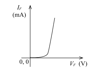
When is plotted against , a characteristic curve similar to Figure 35.2 is obtained.
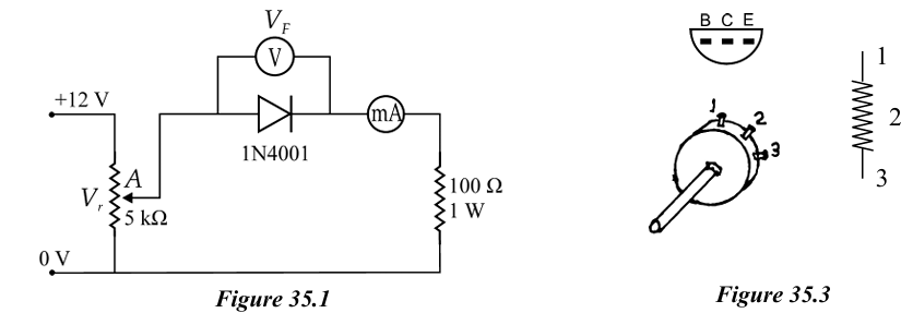
Experimental Method
- Set up the circuit as shown in the theory diagram.
- Rotate the potential divider fully anticlockwise until the potential at terminal A becomes zero.
- Starting from 0.1 V, increase the potential at terminal A gradually.
- At each selected value of , measure and record the corresponding current .
- Record all values in Table 35.1.
- Plot the graph of against .
- Extend the linear portion of the graph backward.
- Determine the voltage (knee voltage) at the point where the graph intersects the axis.
State your conclusion regarding the I-V characteristics of the semiconductor diode.
Important Points
1
- Discuss methods of obtaining more accurate readings in the experiment.
2
- Since the leakage current in reverse bias is of the order of μA, it is difficult to measure accurately.
3
- For the 1N4001 diode, the reverse biased voltage is about 50 V, so leakage current is about 10 μA.
4
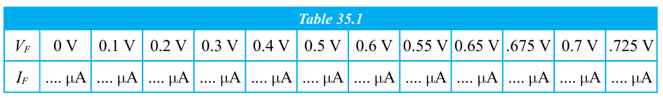
- Use a B-type potentiometer for the 5 kΩ linear potential divider.
5
- The A-type resistor, whose value changes logarithmically, should not be used.
6
- Digital type meters should not be used to set the independent variable, because obtaining stable values is difficult.